Table of contents
- 1. 3.8.1 What is a Virtual Layer 3 Switch?
- 2. 3.8.2 Difference between Bridging & IP Routing
- 3. 3.8.3 Defining Virtual Layer 3 Switches
- 4. 3.8.4 Adding Virtual Interfaces to connect to Virtual Hubs
- 5. 3.8.5 Editing the Routing Table
- 6. 3.8.6 Starting and Stopping Virtual Layer 3 Switches
- 7. 3.8.7 Limitations
- 8. See Also
The virtual layer 3 switch function adds a virtual router which can perform IP routing between multiple Virtual Hubs on the VPN Server, and enables the realization of a layer 3 connection between Virtual Hub segments by carrying out IP routing in accordance with routing rules defined by the Administrator.
3.8.1 What is a Virtual Layer 3 Switch?
Virtual Layer 3 Switch Overview
As described in 3.4 Virtual Hub Functions, the Virtual Hub is an object virtually realizing a physical layer 2 switch (switching hub) using software, and a plurality of Virtual Hubs can be created in the VPN Server. The Virtual Hub only supports the exchange of Ethernet frames on layer 2, and does not support layer 3 routing.
The virtual layer 3 switch was developed and implemented in response to requests to carry out IP routing between layer 2 segments in multiple Virtual Hubs. The virtual layer 3 switch implements as software the functions of communication devices commonly found in the office such as routers and layer 3 switches. The exchange of IP packets between each network is supported by creating multiple Virtual Hubs, separating the layer 2 segments and IP routing between those layer 2 segments.
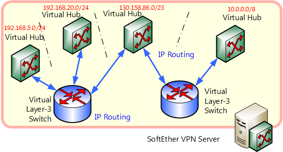
IP Routing between IP Networks with Virtual Layer 3 Switching.
| The virtual layer 3 switch is a function intended for those with an intricate knowledge of networks and IP routing and Network Administrators. Virtual layer 3 switching is not required when using the normal VPN functions. When using the virtual layer 3 switch, sufficient consideration should be given to the impact upon the network, based upon a sound knowledge of IP routing. This explanations contained within this manual assume that the reader possesses such knowledge. |
Virtual Layer 3 Switch Authority
Just as only Administrators of the entire VPN Server can create Virtual Hubs, so does the authority for creating, deleting and setting of virtual layer 3 switch lies solely with said Administrators. Although Virtual Hub Administrators can find out how their own Virtual Hub is connected to the virtual layer 3 switch, they cannot operate or edit the connection of an existing layer 3 switch nor manipulate the routing table. VPN Server Administrators are therefore required to perform settings when using the virtual layer 3 switch function.
3.8.2 Difference between Bridging & IP Routing
Layer 2 network-connecting bridges and cascade connections between Virtual Hubs are mechanisms which connect two separate network segments onto a single network segment. When using TCP/IP protocol within one of the segments, the computers within that segment must, in principle, belong to the same IP network (while it is possible to multiplex a plurality of IP networks on the same segment and make them communicate, computers connected to that network can only communicate directly with those belonging to the same IP network).
In comparison, IP routing is a mechanism which carries out packet exchange on an IP layer between two separate network segments. Please refer to documents on router operation and IP routing for details.
The physical router and layer 3 switch have one IP address for each network segment subject to routing, and forward the IP packet attempting to communicate via that IP address to other suitable interfaces using the routing table held internally by the router.
The VPN Server-definable virtual layer 3 switch operates by the same mechanism. Placing the virtual layer 3 switch between Virtual Hubs on the VPN Server enables IP routing between the Virtual Hubs to which it is connected. In this case, the virtual layer 3 switch has one interface each for segments on both sides. For example, two IP networks 192.168.1.0/24 and 192.168.2.0/24 exist and routing is carried out between them using the virtual layer 3 switch, then an interface is connected to both networks and two IP addresses 192.168.1.254 and 192.168.2.254, for instance, are assigned. When the computer belonging to 192.168.1.0/24 wants to transmit an IP packet to network 192.168.2.0/24, it is possible to send said packet using 192.168.1.254 as a gateway. The router with two interfaces for 192.168.1.254 and 192.168.2.254 then sends this packet to network 192.168.2.0/24. IP routing works by such a mechanism. The theoretical interface on the VPN Server by which the virtual layer 3 switch connects to the Virtual Hub is called the "virtual interface". The connection between the virtual layer 3 switch and the Virtual Hub is actually carried out in the software's internal memory and is not one which can be seen by users. However, a special virtual session known as a virtual layer 3 session is registered on the Virtual Hub to which the virtual layer 3 switch's virtual layer interface is connected.
3.8.3 Defining Virtual Layer 3 Switches
The VPN Server does not have any virtual layer 3 switches in default. Virtual layer 3 switches can be created at any time they are required by the VPN Server Administrator and in any amount.
All virtual layer 3 switches can be named and identified by said name. Alphanumeric characters and some symbols can be used in the name. To define a new virtual layer 3 switch, first select a name. Note that once a virtual layer 3 switch is created, its name cannot be changed.
To carry out settings relating to the virtual layer 3 switch, click the [Layer 3 Switch Setting] button in the VPN Server Manager and display the [Virtual Layer 3 Switch Setting] dialog box. When a virtual layer 3 switch is already registered here, double clicking on it opens up its settings window (all explanations on how to use the virtual layer 3 switch contained herein commence from this window). In the vpncmd utility, use commands starting with "Router" command.
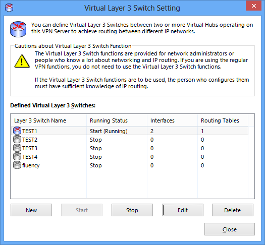
Virtual layer 3 switch setting window.
To create a new virtual layer 3 switch, click the [Create] button and designate its name. A virtual interface must also be defined and the [Start] button clicked before the newly-created virtual layer 3 switch begins running.
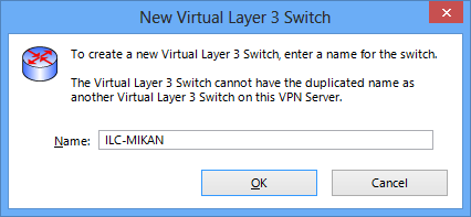
Create virtual layer 3 switch window.
3.8.4 Adding Virtual Interfaces to connect to Virtual Hubs
Simply creating a virtual layer 3 switch serves no purpose, and is comparable to buying a physical router and layer 3 switch and simply leaving them on the shelf. In the same manner as physically connecting a router to the networks of each connection destination with a network cable, it is necessary to register virtual interfaces on the virtual layer 3 switch for the Virtual Hubs of destinations to be connected.
To register a new virtual interface, click the [Add Virtual Interface] button. Once the [Add Virtual Interface] dialog box appears, select the destination Virtual Hub. Also designate the subnet space belonging to the IP address held by that interface within the Virtual Hub.
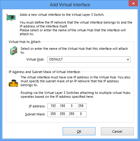
Add virtual interface window.
Multiple virtual interfaces can be created on a virtual layer 3 switch. Normally two or more virtual interfaces are added (only one serves almost no purpose). Register all of the Virtual Hubs to be subject to routing by the virtual layer 3 switch.
| The only Virtual Hubs which can be directly connected to the virtual layer 3 switch are those running on the same VPN Server. When wishing to use layer 3 switching to IP route between a VPN Server on a separate computer or a Virtual Hub running on a VPN Bridge, first create a suitably-named Virtual Hub on the local side and connect it with virtual layer 3 switching, then cascade that Virtual Hub with said VPN Server on a separate computer or said Virtual Hub running on a VPN Bridge. This method enables the connection of remote site Virtual Hubs or physical LANs by virtual layer 3 switching as well as the creation of site-to-site VPN skillfully incorporating an IP routing mechanism. Previously, performing a similar connection required not only a VPN but also involved the purchase of hardware for IP routing. The SoftEther VPN facilitates simple implementation even for networks of sophisticated design by bringing together as software the functions required to connect remote locations to the VPN with IP routing. |
3.8.5 Editing the Routing Table
The virtual layer 3 switch has a routing table similar to that of common physical routers and layer 3 switches. Even without designating anything, if a virtual layer 3 switch has a virtual interface connected to a Virtual Hub, then it has the route information to the IP network determined by the IP address and subnet mask set for that virtual interface. Accordingly, it is not necessary to define a routing table for the layer 2 segment directly connected to the virtual layer 3 switch.
When it is necessary to carry out IP routing via the directly-connected layer 2 segment to an IP network in a segment further ahead, then it is necessary to edit the values of the virtual layer 3 switch's routing table and add suitable routing entries.
The current routing able can be displayed using the [Edit Virtual Layer 3 Switch] dialog box. This table is empty immediately after the creation of a new virtual layer 3 switch. To make new entries in the routing table, click the [Routing Table Entry] button.
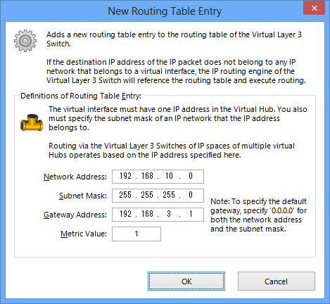
Add routing table entry window.
The [Add Routing Table Entry] window has boxes to enter the details of new routing table entries for registration. The information which needs to be registered here is similar to that designated when adding an entry to the static routing table of a typical router or layer 3 switch. Specific examples of entries are shown below.
- Network Address
Designates the network address including the destination IP address subject to routing using this routing table. - Subnet Mask
Designates the network mask together with the network address. - Gateway Address
Designates the IP address of the IP packet forwarding destination (i.e. the IP address of the next router). The IP addresses which can be designated here must be included in either those IP addresses defined by each virtual interface of this virtual layer 3 switch or among the IP network defined by the subnet mask (note that even those not included are still registered without an error or notification appearing). If another virtual layer 3 switch is connected to an adjacent Virtual Hub, then it may also be the IP address of that virtual layer 3 switch's virtual network interface. - Metric Value
Designates the metric value of the routing table entry.
| When designating the default route, set the network address as 0.0.0.0 and the subnet mask as 0.0.0.0. |
3.8.6 Starting and Stopping Virtual Layer 3 Switches
Start and Stop
Operation can be started for virtual layer 3 switches with one or more registered virtual network interfaces by clicking on the [Start] button. It is also possible to terminate a virtual layer 3 switch during operation at any time by clicking on the [Stop] button.
Note that it is not possible to edit the virtual layer 3 switch's virtual interface list or Routing Table in any mode other than [Terminated]. Therefore, terminate the virtual layer 3 switch to edit these parameters.
Virtual Layer 3 Switch Status
The virtual layer 3 switch has the following three modes and each is displayed in real time in the [Virtual Layer 3 Switch Setting] window.
| Status | Description |
| Stop | Virtual layer 3 switch is stopped. This is the only state in which the virtual layer 3 parameters can be set. |
| Started (operating) | Indicates that the virtual layer 3 switch is running, and that it is functioning because all Virtual Hubs connected to all defined virtual interfaces exist on the VPN Server and are online. This is the only state in which the virtual layer 3 switch can perform IP routing. Also, if even one of the Virtual Hubs connected to the defined virtual interfaces in this mode is deleted from the VPN Server or goes [Offline], then a transition to [Start (error)] mode occurs automatically. |
| Started (error) | Although the virtual layer 3 switch may be set to Started status, when one or more of the Virtual Hubs connected to the defined virtual interfaces does not exist on the VPN Server or is offline then the virtual layer 3 switch cannot commence IP routing. Also, if all of Virtual Hubs connected to the defined virtual interfaces exist on the VPN Server or come online in this mode, then a transition to [Start (operating)] mode occurs automatically. |
3.8.7 Limitations
The virtual layer 3 switch function has the following limitations.
- It does not support dynamic routing protocols.
- It does not support IGMP.
- Sending an ICMP Echo request to the virtual layer 3 switch's virtual interface exceeding 1,472 bytes returns a 1,472 byte ICMP Echo response.
See Also
- 3.4 Virtual Hub Functions
- 6.3.44 "RouterList": Get List of Virtual Layer 3 Switches
- 6.3.45 "RouterAdd": Define New Virtual Layer 3 Switch
- 6.3.46 "RouterDelete": Delete Virtual Layer 3 Switch
- 6.3.47 "RouterStart": Start Virtual Layer 3 Switch Operation
- 6.3.48 "RouterStop": Stop Virtual Layer 3 Switch Operation
- 6.3.49 "RouterIfList": Get List of Interfaces Registered on the Virtual Layer 3 Switch
- 6.3.50 "RouterIfAdd": Add Virtual Interface to Virtual Layer 3 Switch
- 6.3.51 "RouterIfDel": Delete Virtual Interface of Virtual Layer 3 Switch
- 6.3.52 "RouterTableList": Get List of Routing Tables of Virtual Layer 3 Switch
- 6.3.53 "RouterTableAdd": Add Routing Table Entry for Virtual Layer 3 Switch
- 6.3.54 "RouterTableDel": Delete Routing Table Entry of Virtual Layer 3 Switch