Table of contents
- 1. 3.4.1 Creating Virtual Hubs
- 2. 3.4.2 Online & Offline Status
- 3. 3.4.3 Maximum Simultaneous Connections
- 4. 3.4.4 Connection Mode
- 5. 3.4.5 Session Management
- 6. 3.4.6 MAC Address Tables
- 7. 3.4.7 IP Address Table
- 8. 3.4.8 Confirming the Existence of IP Addresses with Poll Packets
- 9. 3.4.9 Communicating in Bridge / Router Mode Session
- 10. 3.4.10 Communicating in Monitoring Mode Session
- 11. 3.4.11 Cascade Connection Functions
- 11.1. Cascade Connections
- 11.2. Creating a Cascade Connection
- 11.3. Online & Offline Status of Cascade Connection
- 11.4. Cascade Connection Security Policies
- 11.5. Creatable Number of Cascade Connections
- 11.6. Cascade Connection Status
- 11.7. Points to Note when Performing a Cascade Connection
- 11.8. Creating, Deleting, Modifying & Controlling a Cascade Connection with the vpncmd Utility
- 12. 3.4.12 Server Authentication in Cascade Connections
- 13. 3.4.13 Local Bridge
- 14. 3.4.14 Administrator Connection
- 15. 3.4.15 Obtaining Information on the Virtual Hubs
- 16. 3.4.16 The Other Options of Virtual Hub
- 17. 3.4.17 Delay and Packet Loss Generating Function
- 18. 3.4.18 Set the Message
- 19. See Also
SoftEther VPN Server makes it possible to create a plurality of Virtual Hubs, and to separate administration objects and VPN session layer 2 communication between each Virtual Hub. This manual explains Virtual Hubs in two parts: general operations & administration methods, and security functions. First is an explanation of the general operations and methods for administration of Virtual Hubs.
3.4.1 Creating Virtual Hubs
Multiple Virtual Hubs can be created in the SoftEther VPN Server, but they can only be created or deleted by entire VPN Server Administrators. When the VPN Server creates a Virtual Hub, it is possible to delegate the authority for its administration to another party by providing them with the Virtual Hub administration password.
To create a new Virtual Hub, click on the [Create Virtual Hub] tab in the VPN Server Manager and enter the relevant details. Alphanumeric characters and some symbols can be used in the Virtual Hub name. It is also possible to designate a Virtual Hub administration password when creating the Virtual Hub (this can also be designated at a later date). Not designating an administration password makes it impossible to carry out remote administration connection to the Virtual Hub in Virtual Hub Administration Mode.
In the vpncmd utility, use the [HubCreate] command. When using the clustering function (refer to 3.9 Clustering), use either the [HubCreateDynamic] or [HubCreateStatic] commands instead.
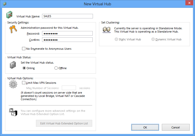
Create New Virtual Hub window.
After creating the Virtual Hub, select it and display the Administration window to carry out administration. Double clicking on the Virtual Hub name in the VPN Server Manager opens a new window for the administration of that hub. In the vpncmd utility, the Virtual Hub can be selected using the [Hub] command. The following explanations of the Virtual Hub all assume that the Virtual Hub's Administration window is open or that the Virtual Hub being administered has been selected using the [Hub].
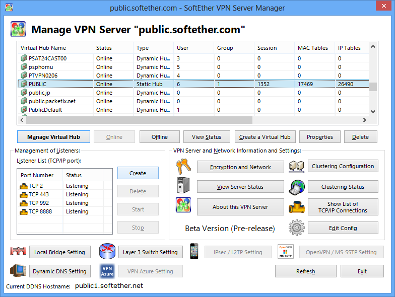
Virtual Hub list screen.
3.4.2 Online & Offline Status
The Virtual Hub has both online and offline status. While the Virtual Hub is normally online, it can also be set to offline status when wishing to temporarily halt its functions.
| Status | Description |
| Online | The mode in which VPN connection to the Virtual Hub from the VPN client computer is possible. In addition, when the Virtual Hub contains cascade connection settings and SecureNAT settings, these functions also operate. Virtual layer 3 switches and local bridge connections associated with the Virtual Hub also run. |
| Offline | The mode in which VPN connection to the Virtual Hub from the VPN client computer is not possible. An error occurs when a VPN connection to the Virtual Hub is attempted. Moreover, all cascade connections and SecureNAT settings within the Virtual Hub cease. Virtual layer 3 switches and local bridge connections associated with the Virtual Hub also stop. When changing a Virtual Hub from online mode to offline mode, first disconnect all of the VPN sessions connected to that Virtual Hub before proceeding. While it may take time for the mode to change, no VPN connections to that Virtual Hub are made in the interim. Although a Virtual Hub in offline mode cannot carry out VPN communication, the administration of the hub can still be performed without any problems. |
To change the Virtual Hub status, open [Virtual Hub property] in the VPN Server Manager and select either [Online] or [Offline] from the [Virtual Hub status] window. In the vpncmd utility, use [Online] or [Offline] command.
3.4.3 Maximum Simultaneous Connections
It is possible to set the maximum number of sessions which can be simultaneously connected to the Virtual Hub. When this value is set, all VPN sessions exceeding the number designated in the Virtual Hub will not be able to connect (all subsequent sessions attempting to connect will be denied).
The number of maximum simultaneous connections does not include local bridge sessions, cascade sessions (virtual sessions created by the cascading side), SecureNAT sessions or virtual layer 3 sessions. That is to say, the maximum number of cascade connections from the VPN Server / VPN Bridge / VPN Client and regular VPN connections connected to the Virtual Hub are limited.
To set the number of maximum simultaneous connections, open the [Virtual Hub properties] window in the VPN Server Manager and check the box in [Limit Max VPN Sessions], then enter the desired value in the [Max Number of Sessions] box. In the vpncmd utility, use the [SetMaxSession] command.
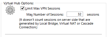
Settings window for maximum simultaneous Virtual Hub connection sessions.
Where the max_sessions, max_sessions_client and max_sessions_bridge options have been set in the Virtual Hub Administration Options, these option values are always applied regardless of whether or not the number of maximum simultaneous connection sessions has been set. See 3.5 Virtual Hub Security Features for details.
3.4.4 Connection Mode
As explained in 1.6 VPN Communication Details, the two types of sessions connected to the Virtual Hub from the VPN source computer are the client mode session and the bridge / router mode session.
3.4.5 Session Management
It is possible to display a list of the VPN sessions currently connected to the Virtual Hub, to display detailed information on each of them, and to forcibly disconnect them.
Displaying Session Lists
A list showing the VPN sessions connected to the Virtual Hub and internally generated sessions can be displayed. Simply clicking on the [Manage Sessions] button in the VPN Server Manager displays a list of the sessions. A session list can also be obtained using the vpncmd utility with the [SessionList] command.
When connecting to a cluster controller using clustering, the sessions displayed in the [Session list] include all of the cluster member server sessions.
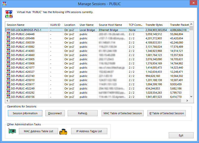
VPN Session administration window.
The following information is shown when displaying a session list.
| Entry | Description |
| Session | The ID to specifically identify the session within the Virtual Hub. The session name starts with "SID-" followed by words indicating the user name and a sequential number. |
| Location | [Local sessions] is displayed when clustering is not in use. When clustering is used, the Cluster Controller session to which that session pertains is displayed. |
| User | The name of the user associated with the session, i.e the name of the user successfully verified when carrying out VPN connection for that session, is displayed. As explained in 2.2 User Authentication, when using asterisk user ("*" user), user authentication is carried out and the name of the user successfully authenticated by the RADIUS server or NT domain controller is displayed here. Where the name on the user database differs from that used in user authentication, the latter is displayed. When the user name is one of the following, that session refers to the special session generated within the VPN Server and not to a regular VPN connection session.
|
| Source Host | In the case of a session generated by a VPN session receiving a regular VPN connection, the host name of the VPN source computer is displayed. The IP address is displayed when reverse DNS resolution fails. |
| TCP Connections | In the case of a session generated by a VPN session receiving a regular VPN connection, the number of TCP/IP connections used in that VPN session's communication is displayed. Please refer to 2.1 VPN Communication Protocol for details on the number of TCP/IP connections. |
| Transfer Bytes | Displays the total data size of virtual Ethernet frames transferred in the current VPN session. |
| Transfer Packets | Displays the total number of virtual Ethernet frames transferred in the current VPN session. |
Distinguishing Session Types with Icons
The session types in the session list display can be differentiated by looking at [User] or by obtaining session information. When using the VPN Server Manager, it is possible to distinguish between session types using the small icons displayed together with the session name.
The following seven icon types are displayed in the session list.
| Icon | Corresponding Session Type |
 | Indicates a general VPN session (i.e. a session created by receiving a routine VPN connection, and not a bridge / router mode or monitoring mode session). |
 | Indicates a bridge/ router mode session. |
 | Indicates a monitoring mode session. |
 | Indicates a local bridge session. |
 | Indicates a cascade connection session. |
 | Indicates a SecureNAT session. |
 | Indicates a virtual layer 3 switch session. |
Obtaining Session Details Data
Double clicking on [Session name] from the session list of the VPN Server Manager displays information relating to that session. The same information can be obtained in the vpncmd utility using the [SessionGet] command.
This enables the identification of detailed information for each session as well as information relating to the source computer (such as its VPN software version and OS).
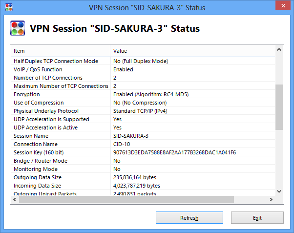
Session details data display window.
Of the detailed session data, the following is important.
| Entry | Description |
| Source IP Address | Displays VPN session's source IP address. |
| Source Host Name | Displays the name of the host obtained by reverse resolution of the source IP address. When reverse resolution fails, the same characters as the [Source IP address] are displayed. |
| User Name (Authentication) | Indicates the name of the user connected to the VPN session. As explained in 2.2 User Authentication, when using asterisk user ("*" user), user authentication is carried out and the name of the user successfully authenticated by the RADIUS server or NT domain controller is displayed here. Where the name on the user database differs from that used in user authentication, the latter is displayed. |
| User Name (Database) | Indicates the name of the user connected to the VPN session. When using asterisk user ("*" user) and when the name on the user database differs from that used in user authentication, the name on the user database is displayed. Where the name on the user database differs from that used in user authentication, the latter is displayed. |
| Server Product Name | Displays the product name of the SoftEther VPN Server accepting the session. |
| Server Version | Displays the version name of the SoftEther VPN Server accepting the session. |
| Server Build | Displays the server build number of the SoftEther VPN Server accepting the session. |
| Connection Start Time | Displays the time that the VPN session connection processing commenced. Note that this is identical to the VPN Server's [Initial session confirm time] and [Current session confirm time]. |
| Half-duplex TCP Connection Mode | Indicates whether or not the SoftEther VPN protocol's communication mode in the VPN session is half-duplex connection mode. |
| VoIP / QoS Function | Indicates whether or not the VoIP / QoS support function (see 1.9 VoIP / QoS Support Function for details) is valid in this session. |
| Number of TCP Connections | Displays the current number of TCP/IP connections constituting the VPN session. |
| Maximum Number of TCP Connections | Displays the maximum number of TCP/IP connections which can be used to constitute the VPN session. |
| Encryption | Indicates whether the VPN session is protected by encryption and electronic signature. |
| Use of Compression | Indicates whether or not communication compressed by data compression algorithms is being used. |
| Session Name | Indicates the ID to identify the session. |
| Session Key (160bit) | Indicates the internal administration ID to specifically identify the session created by the VPN Server. |
| Bridge / Router Mode | Indicates whether the session type is a bridge / router mode session. |
| Monitoring Mode | Indicates whether the session type is a monitoring mode session. |
| Outgoing Data Size | The bytes of data transmitted from the VPN source to the VPN Server on the SoftEther VPN protocol (indicates the approximate actual physical packet volume flowing over the IP network). |
| Incoming Data Size | The bytes of data transmitted from the VPN Server to the VPN source on the SoftEther VPN protocol (indicates the approximate actual physical packet volume flowing over the IP network). |
| Statistical Information | Indicates the sent/received virtual Ethernet frame type packets and total data size (updated in real time). |
| Client Product Name | Indicates the name of the VPN source software. |
| Client Version | Indicates the version number of the VPN source software. |
| Client OS Name & Version | Indicates the name and version of the operating system on which the VPN source software is running. |
| Client Host Name | Indicates the client computer's host name as notified by the VPN source software. |
| Client Port | Indicates the client's TCP/IP port number as notified by the VPN source software. |
| Server Host Name | Indicates the name of the designated server that the VPN source software is attempting to connect to. |
| Server IP Address | Indicates the IP address as a result of forward resolution of the designated server name that the VPN source software is attempting to connect to. |
| Server Port | Indicates the port number of the designated server that the VPN source software is attempting to connect to. |
| Proxy Host Name | Indicates the host name of the proxy server when the VPN source software is using a proxy server to connect to the VPN. |
| Proxy IP Address | Indicates the IP address of the proxy server when the VPN source software is using a proxy server to connect to the VPN. |
| Proxy Port | Indicates the TCP/IP port number of the proxy server when the VPN source software is using a proxy server to connect to the VPN. |
Forced Disconnect of Session
It is possible for Virtual Hub Administrators to forcibly disconnect a connected session. To disconnect a session, simply select the session to be disconnected in the VPN Server Manager and click the [Disconnect] button. In the vpncmd utility, use the [SessionDisconnect] command.
3.4.6 MAC Address Tables
As explained in 1.6 VPN Communication Details, the Virtual Hub supports the exchange of virtual Ethernet frames between sessions by automatically learning the MAC address table and associating the addresses with their corresponding connected session. The Virtual Hub Administrators can display the contents of the latest Virtual Hub MAC address table.
Displaying Virtual Hub MAC Address Tables
Clicking on the [MAC address Table List] button in the [Manage Sessions] window of the VPN Server Manager displays the MAC address tables. In the vpncmd utility, the table can be obtained using the [MacTable] command.
When requesting MAC address tables from the cluster controller in a cluster environment, the cluster controller responds with MAC address tables on all of the cluster member servers together.
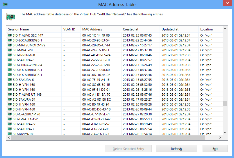
MAC address table administration window.
The entries listed for each record (MAC address entry) in the MAC address table are as follows.
| Entry | Description |
| Session Name | Indicates the session name associated with the MAC address entry. |
| MAC Address | The actual MAC address shown by the MAC address entry. |
| Created Time | Displays the time and date on which the entry was created in the MAC address table. |
| Updated Time | Displays the time & date on which the existence of the network node with the subject MAC address was confirmed in the session to which the Virtual Hub last responded. MAC address entries on which 600 seconds have elapsed since the update are deleted from the table at the next aging-time. |
| Location | Indicates the name of the VPN Server host within which that MAC address table actually exists within the cluster. |
Deleting Virtual Hub MAC address tables
Although not normally required, the Virtual Hub Administrator can arbitrarily delete MAC address table entries. To delete a MAC address table entry, select the entry with the VPN Server Manager and click the [Delete selected entry] button. In the vpncmd utility, the entry can be deleted using the [MacDelete] command.
Listing the MAC Address Table associated with a Specific Session
In the VPN Server Manager's [Manage Sessions] window, select the desired session and click [MAC table of This Session] button. This displays a list of only those MAC address table entries associated with the selected session. It is also possible to designate a session and find out which MAC addresses are being used by the VPN client computer for that session. The same task can be carried out using the vpncmd utility by attaching the session name as an argument to the [MacTable] command.
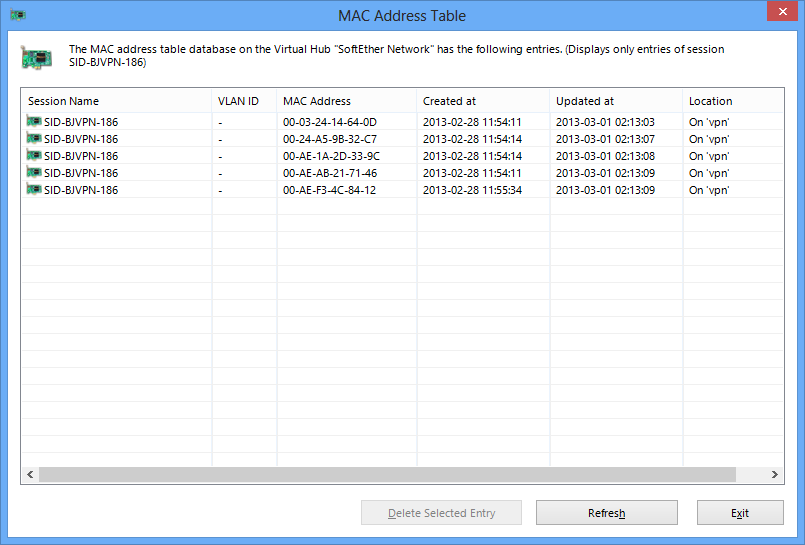
Session-specific MAC address table.
3.4.7 IP Address Table
The Virtual Hubs automatically create and administer MAC address tables, but when the virtual Ethernet frames transmitted in the VPN are IP packets, they also automatically learn and session-associate not only the MAC addresses but also the IP addresses at the same time by reading the IP packet header. The internal table for this purpose is a database called the IP address table.
While the IP address table is not used for virtual Ethernet frame switching between sessions, it is possible to apply rigorous security policies to each user by supporting real-time data on which session sent packets based on which IP address thus far.
The Virtual Hub Administrators can display the contents of the latest Virtual Hub MAC address table. This makes it possible to find out at any time which VPN session computer is communicating using which IP address.
Displaying Virtual Hub IP Address Tables
Clicking on [IP Address Table List] button in [Manage Sessions] window of the VPN Server Manager displays the IP Address Table. In the vpncmd utility, the table can be obtained using the [IpTable] command.
When requesting IP address tables from the cluster controller in a cluster environment, the cluster controller responds with IP address tables on all of the cluster member servers together.
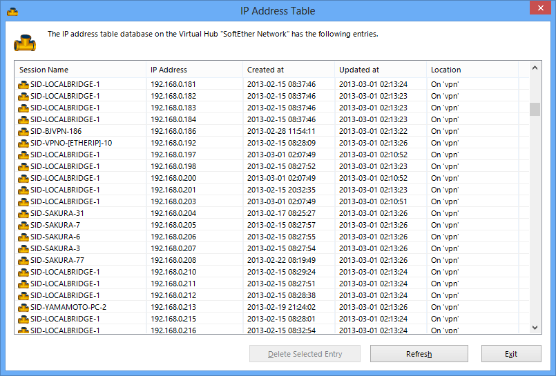
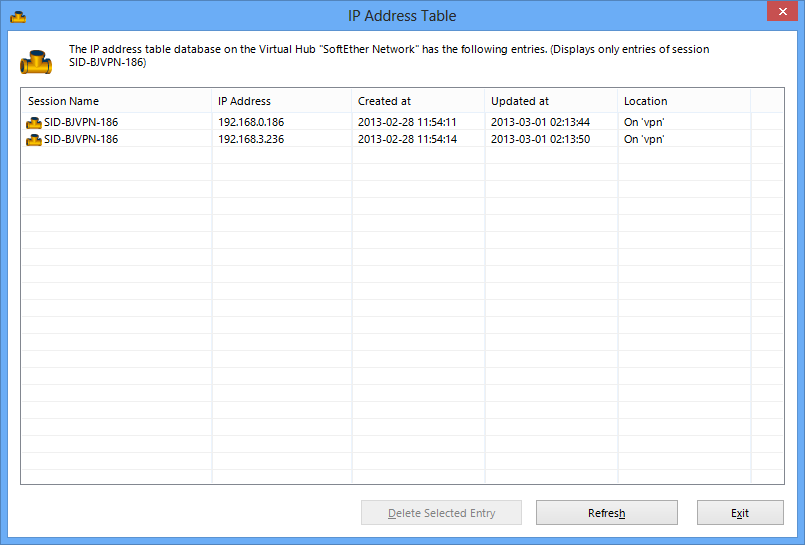
IP address table administration window.
The entries listed for each record (IP address entry) in the IP address table are as follows.
| Entry | Description |
| Session Name | Indicates the session name associated with the IP address entry. |
| IP Address | The actual IP address shown by the IP address entry. "(DHCP)" may appear in the portion after the IP address. This indicates that the IP address is one assigned by the DHCP Server in the VPN. |
| Created Time | Displays the time & date on which the entry was created in the IP address table. |
| Updated Time | Displays the time & date on which the existence of the network node with the subject IP address was confirmed in the session to which the Virtual Hub last responded. IP address entries on which 60 seconds have elapsed since the update are deleted from the table at the next aging-time. |
| Location | Indicates the name of the VPN Server host within which that IP address table actually exists within the cluster. |
Deleting Virtual Hub IP Address Tables
Although not normally required, Virtual Hub Administrators can arbitrarily delete IP address table entries. To delete an IP address table entry, select the entry with the VPN Server Manager and click the [Delete selected entry] button. In the vpncmd utility, use the [IpDelete] command.
Listing the IP Address Table associated with a Specific Session
In the VPN Server Manager's [Manage Sessions] window, select the desired session and click [IP Table of This Session] button. This displays a list of only those IP address table entries associated with the selected session. This makes it easy to find out which IP addresses are being used by the VPN client computer for a designated session. The same task can be carried out using the vpncmd utility by attaching the session name as an argument to the [IpTable] command.
For VPN sessions where a router is connected at the session destination, all of the IP addresses of packets arriving from the other side of the router (such as the Internet) may be associated. This is because there is no way to distinguish whether each IP address in a Virtual Hub operating in layer 2 has been routed via a router or whether they have been transmitted from a node directly connected by layer 2.
Session-specific IP address table.
3.4.8 Confirming the Existence of IP Addresses with Poll Packets
As explained in 3.4.7, the Virtual Hubs have IP address table databases to constantly administer which sessions are communicating using which IP addresses. Additionally, in order to check whether an IP address registered on the IP address table database actually exists on the layer 2 local segment to which the Virtual Hub belongs, poll packets to confirm the existence of the IP address (survey packets) are sent out at regular intervals using the ARP protocol, and those IP address table entries which respond have their expiration date updated, while those entries which do not respond are deleted from the IP address table database after a certain period (60 seconds), thereby maximizing the accuracy of IP address existence confirmation.
At this time, the Virtual Hub sends a unicast of the ARP request packet for the known IP address to the corresponding session based on the IP address table entry. The sending IP address for this ARP request packet is "172.31.0.0/16" and the destination IP address is the IP address subject to the survey.
This operation normally allows ongoing verification of IP address lists on the layer 2 segment, but some operating systems (including FreeBSD) receiving an ARP packet with the sending IP address of "172.31.0.0/16" simply do not respond or leave a warning message in their syslog etc. stating that they received an unauthorized ARP packet with a sending IP address of "172.31.0.0/16".
While there is typically no problem with ignoring such warning messages, it is possible to stop the poll packet confirming the existence of IP addresses when many computers running BSD exist on the same segment and complaints start to arrive from the Administrators. To stop the poll packet from confirming the existence of IP addresses in a Virtual Hub, rewrite the VPN Server's Configuration file as follows.
Because [false] is set as the default for [NoArpPolling] within the [Virtual Hub] [Virtual Hub name] [Options] nodes in the Configuration file, rewrite this to [true].
	declare Option
	{
		uint MaxSession 0
		bool NoArpPolling true
		bool NoEnum false
} |
Changing this setting as above stops the Virtual Hub from regularly unicasting poll packets using the ARP protocol.
Setting NoArpPolling to true means that there is no guarantee that the contents of the IP address database administered by the Virtual Hub are up-to-date. As such, it is possible that the following items from the user and group security policy items will not be applied correctly, and as such, the following security policy items should not be used when using the Virtual Hubs with NoArpPolling set to true.
Please refer to 3.5 Virtual Hub Security Features for details on security policy items.
- [Enforce DHCP Allocated IP address] policy
- [Deny MAC Address Duplication] policy
- [Deny IP address Duplication] policy
- [Maximum Number of IP addresses] policy
3.4.9 Communicating in Bridge / Router Mode Session
As explained in 1.6 VPN Communication Details, bridging and routing is denied for VPN Client-connected sessions in client mode sessions. Accordingly, it is possible to protect against actions such as unauthorized bridge connections and routing between the virtual Network Adapter and the physical network adapter connected to a VPN session on the computer on which the VPN Client is installed.
When the VPN Client enables the [Bridge / Router Mode] in the [Advanced Settings] connection settings tab or in the case of a cascade connection from the VPN Server / VPN Bridge, the session is connected using the Bridge / Router Mode. For sessions connected by the Bridge / Router Mode, basically all communication is permitted regardless of the size of layer 2 network to which it is bridged at that session destination (connection source side), when routed to the Internet and even when cascade connected to another Virtual Hub.
Please refer to 4.4 Making Connection to VPN Server, for specific methods to connect the VPN Client to a Virtual Hub in Bridge / Router Mode.
3.4.10 Communicating in Monitoring Mode Session
As described in 1.6 VPN Communication Details, when a monitoring mode session is connected to a Virtual Hub, all virtual Ethernet frames flowing within the Virtual Hub are automatically copied and distributed to the monitoring mode session. As such, it is possible to intercept all virtual Ethernet frames flowing within a Virtual Hub when connected to the Virtual Hub via a monitoring mode session. This comes in handy for Network Administrators when troubleshooting and setting up an IDS.
Although a monitoring mode session can receive all communication within a Virtual Hub, it can not transmit communication to the Virtual Hub.
Please refer to 4.4 Making Connection to VPN Server for specific methods to connect the VPN Client to a Virtual Hub in monitoring mode.
| When the number of virtual Ethernet frames flowing within the Virtual Hub exceeds the processing capacity of the computer and its peripheral devices or when the frame buffer does not have enough available memory, the SoftEther VPN Server software may discard those frames to protect overall system stability. That is why it may not be possible to receive all frames depending on the circumstances. |
3.4.11 Cascade Connection Functions
Cascade Connections
The mechanisms of and methods for creating cascade connections are very important in creating a site-to-site VPN using SoftEther VPN.
Using the cascade connection function enables the cascade connection of a Virtual Hub within the VPN Server to other Virtual Hubs operating on the same or separate computers.
When two Virtual Hubs are running on separate computers or even when they are running on the same computer, those hubs are originally not connected in any way so they are two completely isolated segments from the perspective of a layer 2 network. However, in many cases there may be a desire to run two Virtual Hubs as a single segment over a public IP network such as the Internet. For instance, a cascade connection is essential to build a site-to-site VPN (see 1.4 VPN Processing Principle and Communication Method). Using a cascade connection enables the connection of two or more Virtual Hubs as if connecting them with a very long network cable.
Cascading a remotely located Virtual Hub A with Virtual Hub B enables free layer 2 (Ethernet level) communication between a Virtual Network Adapter connected to A and a network computer locally bridged to A and a network adapter connected to B and a network computer locally bridged to B. In other words, the computers connected to each other's Virtual Hubs can communicate freely on a layer 2 level irrespective of the actual network topology, wherein that connection may be a virtual one by the VPN Client, or a physical network adapter's destination may be locally bridged to a Virtual Hub and that Virtual Hub is cascade connected to yet another hub so as to arrive at the destination computer.
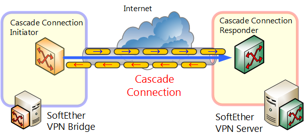
Cascade connection between Virtual Hubs.
Cascading obviously requires the existence of two Virtual Hubs, i.e. a Virtual Hub to initiate the cascade connection and a Virtual Hub to receive it. From the perspective of the Virtual Hub receiving the cascade connection, the incoming connection is processed as a common VPN session (bridge / router mode session), in which case user authentication is required just as though a VPN Client were carrying out a VPN connection to a Virtual Hub.
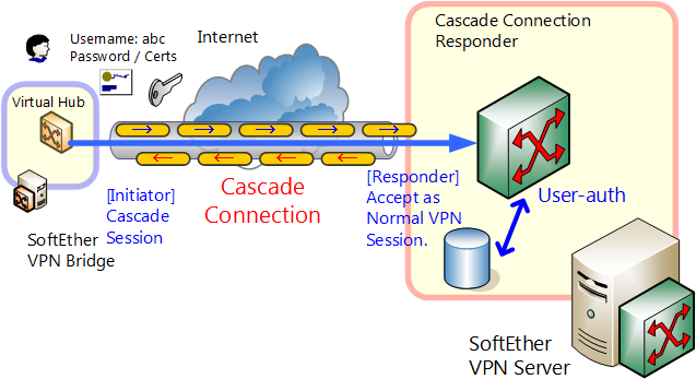
Initiating & receiving cascade connection.
Creating a Cascade Connection
To create a cascade connection for a Virtual Hub to another Virtual Hub, click on the [Manage Cascade Connections] button in the VPN Server Manager. This displays [Cascade Connection on "Virtual Hub name"] window. Next click on [Create] and enter the relevant details for the VPN Server host name, Virtual Hub and user authentication. It is also possible to make the VPN connection via a HTTP or SOCKS proxy server in addition to using a direct TCP/IP connection when cascading.
The items to be entered when creating a new cascade connection are practically the same as those required for a creating a new VPN Client connection setting. Please therefore refer to 4.4 Making Connection to VPN Server for the meanings of each item.
All user authentication methods are available for cascade connections except smartcard authentication.
| The cascade connection settings are created on the Virtual Hub performing the cascade, and it is not necessary to create a cascade connection on the receiving Virtual Hub. Therefore, when cascading Virtual Hubs on two VPN Servers, both the initiating side and receiving side should be selected before creating the connection. When cascading a VPN Server's Virtual Hub and VPN Bridge, the Virtual Hub must be set as the receiving side and a VPN Bridge Virtual Hub with the name "BRIDGE" must be set as the initiating side. This is because the VPN Bridge cannot receive VPN connections including cascade connections. A cascade connection user must be created in advance on the Virtual Hub receiving the cascade connection in order to enable receipt of the cascade. That user name and authentication information must then be designated when creating a new cascade connection on the Virtual Hub initiating the cascade. |
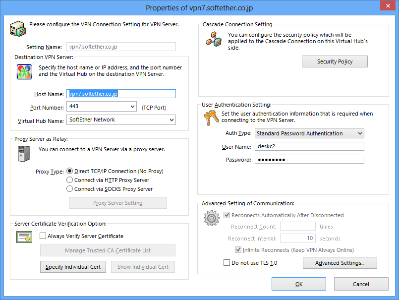
Cascade connection create & edit window.
Online & Offline Status of Cascade Connection
Upon creating a new cascade connection on a Virtual Hub, that cascade connection is offline. It is not possible to communicate on a cascade connection which is offline. To start communication using a cascade connection, select the desired cascade connection in the [Cascade Connection on "Virtual Hub name"] window of the VPN Server Manager and click the [Online] button.
Upon setting the cascade connection to online status, the Virtual Hub attempts to maintain the cascade connection as far as possible in line with the cascade connection settings. The cascade is successful once the connection to the destination VPN Server Virtual Hub is confirmed, and [Online (connected)] appears in the [Status] display. When an error occurs, the error code will appear in this [Status] display. When the cause of the error is attributed to an input error in the cascade connection settings, first take the cascade connection offline, correct the connection settings by clicking on the [Edit] button, and click the [Online] button once again.
As explained in 2.1 VPN Communication Protocol on reconnect settings where the VPN connection fails or is disconnected during communication, an attempt to reconnect is made every 10 seconds when the VPN session connection fails or is disconnected while cascading. In this way, the Virtual Hub attempts to maintain a constant connection with the cascade destination Virtual Hub as far as the latter's network allows.
Any change in the cascade connection status is recorded on the VPN Server's server log and Virtual Hub security log. Regularly checking these logs provides knowledge on cascade connection success and failure records and enables an understanding of the line status. Please refer to 3.10 Logging Service for details on how to view the VPN Server's server log and Virtual Hub security log.
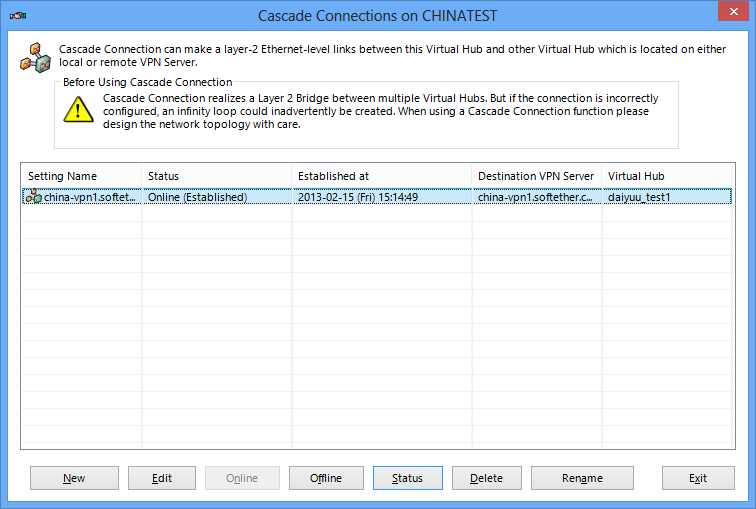
Cascade connection management window.
Cascade Connection Security Policies
Security policies can be set as desired for cascade connection users so that the virtual Ethernet frames which travel over the cascade connection are subject to scrutiny on the hub receiving the cascade.
To apply security policies in relation to the virtual Ethernet frames which travel over the cascade connection on the hub initiating the cascade, click on the [Security policy] button in the cascade connection's connection settings window and set as desired.
However, some policies affect the packets sent to that session. Please regard to the description of each policy.
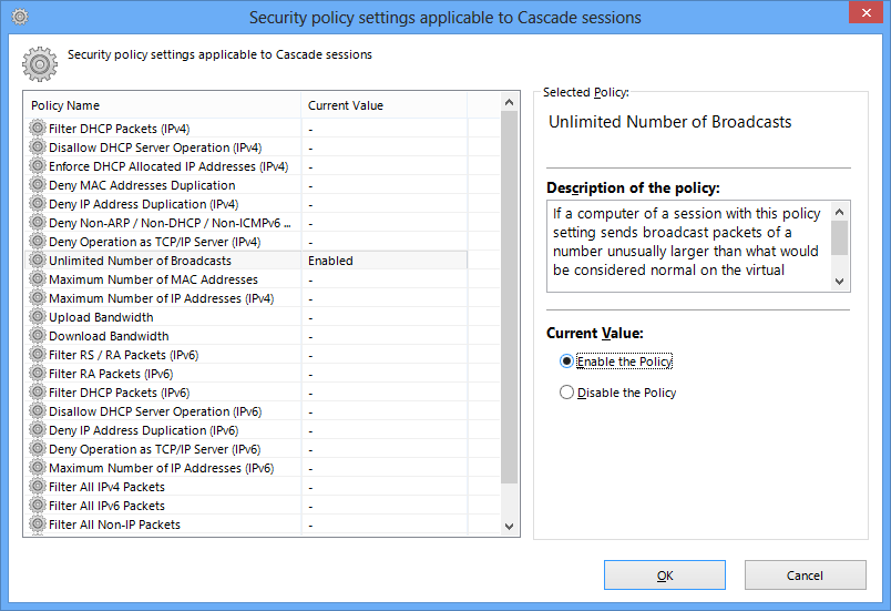
security policy settings applicable to Cascade sessions window.
Creatable Number of Cascade Connections
A maximum of 128 cascade connections can be created in a Virtual Hub, although in reality, it is not necessary to connect a large amount of cascade connections from a single Virtual Hub.
Cascade Connection Status
The cascade connection status of the hub initiating the cascade can be obtained at any time. Selecting the desired cascade connection in the [Cascade Connection on "Virtual Hub name"] window of the VPN Server Manager and clicking the [Status] button displays the communication status for that cascade connection session in real time. The communication status displayed here is virtually the same as the connections settings' communication status shown in the VPN Client Manager. For details, please refer to 4.5 Connect to VPN Server.
The hub receiving the cascade connection recognizes it as being a Bridge / Router Mode session, which means that it is shown in the Virtual Hub session list. Note that the cascade is not automatically displayed in the [Cascade connection] list of the receiving hub. For details, please refer to 3.4.5.
Points to Note when Performing a Cascade Connection
Cascading is a very convenient and useful function without which the value of the SoftEther VPN software would be halved. However, the following points should be observed in order to use the cascade connection properly.
- Before creating the cascade connection, careful consideration should be given to the design of the VPN network topology and notes should be taken to ensure the connection is used in a suitable manner. For instance, where three Virtual Hubs are each attached to their own site and those sites are in turn locally bridged to a physical LAN, cascading each of the Virtual Hubs results in a looped layer 2 network topology which can cause communication paralysis and give rise to broadcast storms. As such, any actions which result in the creation of a layer 2 loop should definitely be avoided when using the cascade connection.
- The SoftEther VPN Server's cascade connection function does not support the Spanning Tree Protocol.
- It is necessary to create a cascade connection setting for the Virtual Hub performing the cascade connection and to put it online. It is necessary to predefine the users to receive the cascade connection on the receiving Virtual Hub.
- The hub initiating the cascade treats the cascade connection the same as it treats a VPN connection by the VPN Client, so the settings for creating a cascade connection are similar to those for creating a new connection on the VPN Client.
Creating, Deleting, Modifying & Controlling a Cascade Connection with the vpncmd Utility
To control the cascade connection with the vpncmd utility, use commands beginning with "Cascade". These commands enable the same tasks performed by VPN Server Manager's GUI settings to be carried out with the vpncmd utility. Please refer to 6.4 VPN Server / VPN Bridge Management Command Reference (For Virtual Hub) for details on how to control a cascade connection using the vpncmd utility.
3.4.12 Server Authentication in Cascade Connections
Server authentication processing by the inspection of server certificates as explained in 2.3 Server Authentication is also supported for cascade connections in a manner similar to that of a VPN Client connection, whereby it is possible to check whether the cascade destination VPN Server has the proper certification when connecting.
To register the destination VPN Server's certificate, click the [Specify individual Cert] button in the cascade connection settings' edit window and select an arbitrary X.509 certificate. When using signed certificate authentication, register a trusted root certificate (or intermediate certificate) in the cascade-initiating Virtual Hub's [Trusted certification authority certificates].
| Signed certificate authentication is not available as one of the server authentication methods when making a cascade connection from a SoftEther VPN Bridge Virtual Hub (with the fixed name "BRIDGE") to the SoftEther VPN Server. This is a restriction imposed by the SoftEther VPN Bridge. |
3.4.13 Local Bridge
The setting of the local bridge function as explained in 1.4 VPN Processing Principle and Communication Method can only be performed by the entire SoftEther VPN Server Administrator. It is therefore not possible to bridge a Virtual Hub and a physical network adapter of the computer running the VPN Server with Virtual Hub Administrator authority alone. For details on how to create and delete local bridges, please refer to 3.6 Local Bridges.
3.4.14 Administrator Connection
Multiple users and groups can be added to a Virtual Hub (please refer to 3.4.3 for specific administration methods). Remotely connecting to a Virtual Hub over a VPN typically requires the designation of a user name registered in advance by the Virtual Hub Administrator.
The exception to this is when a Virtual Hub Administrator designates Administrator as the user and that Virtual Hub's Administrator password as the password to enable the VPN connection. This VPN connection is always possible even when no users exist on the Virtual Hub. Virtual Hub Administrators can therefore make a VPN connection to the Virtual Hub for which they are responsible at any time (cascade connections from the VPN Server / VPN Bridge are possible in addition to connection from the VPN Client).
The Administrator user is special and this user name cannot be manually added to a Virtual Hub.
The following security policies are applied to VPN connection to a Virtual Hub by the Administrator.
- [No Limit on Number of broadcasts] is enabled
- [Allow Monitoring Mode] is enabled
All other security policies therein are regarded as default security policies (please see 3.5 Virtual Hub Security Features).
Accordingly, Administrators can always make a VPN connection to the Virtual Hub with the minimum amount of limitations. VPN connections are also possible with [Monitoring Mode] enabled.
3.4.15 Obtaining Information on the Virtual Hubs
Virtual Hub Administrators can acquire the latest information on the Virtual Hubs by accessing [View status] in the Virtual Hub administration window. Clicking on the [Refresh] button provides an understanding of the Virtual Hub's status as it changes in real time.
In the vpncmd utility, Virtual Hub information can be obtained using the [StatusGet] command.
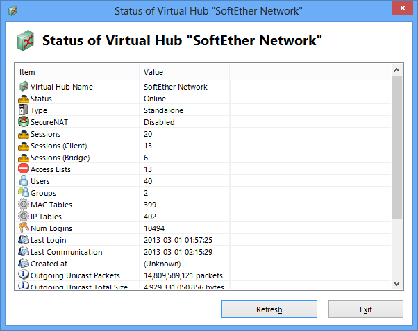
Virtual Hub information display window.
3.4.16 The Other Options of Virtual Hub
As not described the past manuals, changing VPN Server configuration file, the items are described below. These items are for users with detailed knowledge of network system and computers.
These entries are false at default. To set true, after stopping VPN Server service, update [Virtual Hub][Virtual Hub Name][Option] in vpn_server.config, VPN Server configuration file.
| Entry | Description |
| NoIpTable | When this entry is true, virtual Hub does not create and manages IP address table. The communication speed is increased in virtual Hub because the virtual Hub does not interpret IP layer packets. |
| ManageOnlyPrivateIP | When this entry is true, virtual Hub registers private IP address only on IP address table. The others are not registered. |
| FilterPPPoE | When this entry is true, virtual Hub discards All PPPoE (PPP over Ethernet) packets. |
| FilterOSPF | When this entry is true, virtual Hub discards All OSPF (Open Shortest Path First) packets. |
| YieldAfterStorePacket | When this entry is true, after a thread storing the packets sent queue to destination session, virtual Hub yields the session, then passing over CPU time. Due to this entry set true, communication speed may be increased. |
3.4.17 Delay and Packet Loss Generating Function
This function can generate delays, jitters and packet losses on packets which match the condition of this access list entry when transmitted via this Virtual Hub. This function is convenient to simulate a low-quality and slow Internet, WAN or wireless connections on the desk or laboratory. For example, you can use it to evaluate and test IP telephonies (VoIP).
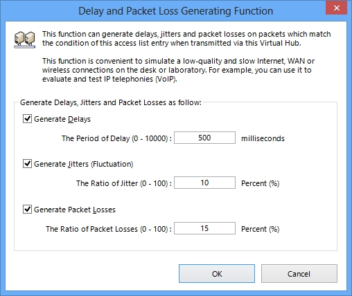
Delay, Jitter and Packet Loss Generator
3.4.18 Set the Message
You can set a message to display on the screen of a user when a VPN Client connects to the Virtual Hub "%S". To show a message, input the message that you want to show. Specify a single line starts with "http://" as the message to open the default Web browser on the client instead to showing a message.
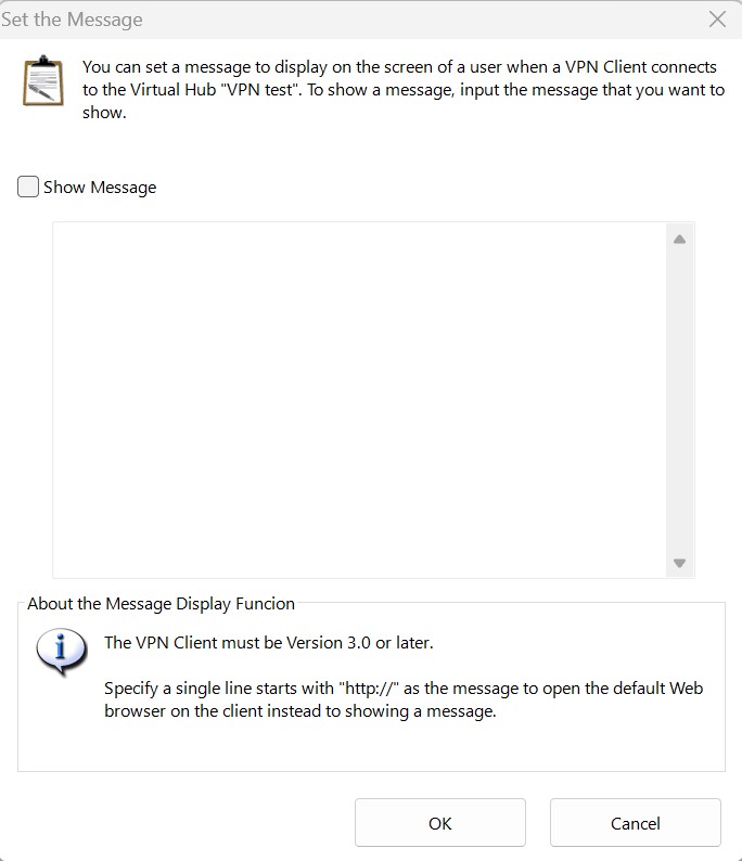
Set the message
See Also
- 1.4 VPN Processing Principle and Communication Method
- 1.6 VPN Communication Details
- 1.9 VoIP / QoS Support Function
- 2.1 VPN Communication Protocol
- 2.2 User Authentication
- 2.3 Server Authentication
- 3.5 Virtual Hub Security Features
- 3.6 Local Bridges
- 3.9 Clustering
- 3.10 Logging Service
- 4.4 Making Connection to VPN Server
- 4.5 Connect to VPN Server
- 6.3.57 "HubCreate": Create New Virtual Hub
- 6.3.58 "HubCreateDynamic": Create New Dynamic Virtual Hub (For Clustering)
- 6.3.59 "HubCreateStatic": Create New Static Virtual Hub (For Clustering)
- 6.4 VPN Server / VPN Bridge Management Command Reference (For Virtual Hub)
- 6.4.1 "Online": Switch Virtual Hub to Online
- 6.4.2 "Offline": Switch Virtual Hub to Offline
- 6.4.3 "SetMaxSession": Set the Max Number of Concurrently Connected Sessions for Virtual Hub
- 6.4.82 "SessionList": Get List of Connected Sessions
- 6.4.83 "SessionGet": Get Session Information
- 6.4.84 "SessionDisconnect": Disconnect Session
- 6.4.85 "MacTable": Get the MAC Address Table Database
- 6.4.86 "MacDelete": Delete MAC Address Table Entry
- 6.4.87 "IpTable": Get the IP Address Table Database
- 6.4.88 "IpDelete": Delete IP Address Table Entry