Table of contents
- 1. 10.6.1 Combining Bridge Connections and IP Routing
- 2. 10.6.2 IP Routing Via Virtual Layer 3 Switching
- 3. 10.6.3 Pros and Cons of IP Routing
- 3.1. IP Routing - Pros
- 3.2. IP Routing - Cons
- 4. 10.6.4 Network Layout
- 5. 10.6.5 Installing VPN Server On the Main LAN
- 6. 10.6.6 Installing VPN Bridge on the Other LANs
- 7. 10.6.7 LAN-to-LAN VPN Connection
- 8. 10.6.8 Supplementary Information
- 9. See Also
This section will explain how to create a layer 3 connection between two or more remote networks by utilizing bridge connections together with IP routing.
10.6.1 Combining Bridge Connections and IP Routing
After reading section 10.5 Build a LAN-to-LAN VPN (Using L2 Bridge) you know how to connect multiple LANs together into a single layer 2 (Ethernet) segment, forming a LAN-to-LAN VPN.
By combining that method and the Virtual Layer 3 Switching capability built into VPN Server you can construct a LAN-to-LAN VPN that utilizes layer 3 IP routing.
10.6.2 IP Routing Via Virtual Layer 3 Switching
VPN Server has Virtual Layer 3 Switching capabilities which allow it to perform IP routing between multiple Virtual Hubs under the same VPN Server. By using this capability you can construct a large scale LAN-to-LAN VPN which works even if each individual LAN has multiple IP networks of its own.
Please refer to section 3.8 Virtual Layer 3 Switches for a summary of Virtual Layer 3 Switching and how to use it.
10.6.3 Pros and Cons of IP Routing
This section will give the pros and cons of setting up a LAN-to-LAN VPN that performs IP routing between LANs through Virtual Layer 3 Switching as opposed to setting up one using only bridge connections as explained previously in section 10.5 Build a LAN-to-LAN VPN (Using L2 Bridge).
IP Routing - Pros
- Using only bridge connections to make a VPN connection to multiple LANs results in those LANs being joined together as a single layer 2 (Ethernet) segment. By also utilizing Virtual Layer 3 Switching you can perform layer 3 (IP) communication between LANs even if they are separated at a layer 2 level.
- This means that you will be able to communicate between LANs that already have their own stable IP networks without making any changes to the computers/devices on those networks.
- It's also a good idea to use IP routing when dealing with large LANs that contain more than 100 computers each. When simply bridging multiple LANs together there could be an increase in broadcast packet traffic due to the increased number of computers on the network. In this case it's best to use IP routing to perform routing between the LANs and create a smaller broadcast domain.
IP Routing - Cons
- A good knowledge of TCP/IP and VPNs is required to configure Virtual Layer 3 Switching and design/build a LAN-to-LAN VPN that utilizes IP routing.
- You may also notice a slight performance decrease in layer 3 compared to a simple layer 2 LAN-to-LAN VPN due to the routing processing (such as re-writing IP headers, etc.) which must transfer large numbers of packets in bursts.
- Because each LAN's layer 2 segments are separated, they can only communicate to each other via IP.
10.6.4 Network Layout
This section will explain the following type of network layout as an example.
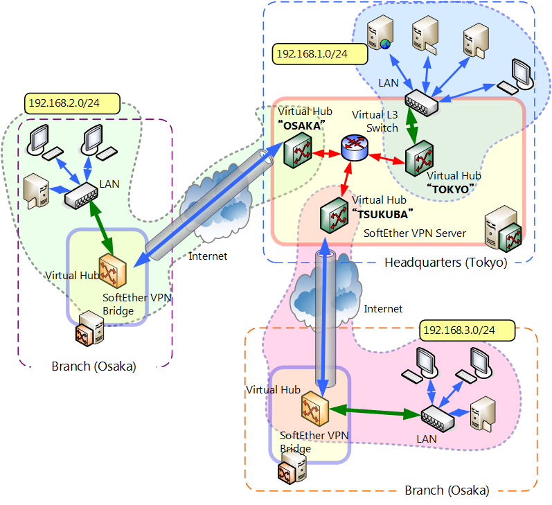
Network Layout.
In the above network example there are 3 LANs connected together through a VPN connection. Computers on all LANs are able to communicate with each other through the IP routing enabled VPN. For this example, assume that the three LANs are located in Tokyo, Osaka, and Tsukuba, Japan.
The Tokyo LAN is the main LAN and therefore VPN Server is installed there. This leaves the LANs in Osaka and Tsukuba as the sub-LANs. VPN Bridge will be installed to both of these locations.
The private IP networks in Tokyo, Osaka, and Tsukuba are separated as 192.168.1.0/24, 192.168.2.0/24, and 192.168.3.0/24 respectively. When a computer from one LAN attempts to communicate with a host on another LAN it will automatically do so through the VPN.
Virtual Hubs on the VPN Server
In the above network the layer 3 switch operates on the VPN Server in Tokyo. When creating this network the following three Virtual Hubs should be made on the Tokyo LAN VPN Server.
- TOKYO
"TOKYO" will be the Virtual Hub that makes a local bridge connection to the network that the VPN Server is physically connected to. In this case, the Tokyo LAN. On a layer 3 level, this Virtual Hub is part of the 192.168.1.0/24 IP network. - OSAKA
"OSAKA" will be the Virtual Hub that handles the cascade connection from the VPN Bridge on the Osaka LAN. Therefore, this Virtual Hub is on the same layer 2 segment as the Osaka LAN. On a layer 3 level, this Virtual Hub is part of the 192.168.2.0/24 IP network. - TSUKUBA
"TSUKUBA" will be the Virtual Hub that handles the cascade connection from the VPN Bridge on the Tsukuba LAN. Therefore, this Virtual Hub is on the same layer 2 segment as the Tsukuba LAN. On a layer 3 level, this Virtual Hub is part of the 192.168.3.0/24 IP network.
Layer 3 Switches on the VPN Server
After the three Virtual Hubs above have been created on the VPN Server in Tokyo, you need to create a single Virtual Layer 3 Switch while looking to section 3.8 Virtual Layer 3 Switches for reference. Once this is done you have to define a virtual interface to the three Virtual Hubs.
The Virtual Layer 3 Switch will look like a single IP router to computers on the network. Therefore, you will need to assign a single IP address that belongs to the private network receiving Virtual Hub connections to each virtual interface. The IP address must be one that does not exist on any of the IP networks directly or indirectly connected to by each of the Virtual Hubs. For example, you could set up something like the table below.
| Virtual Hub Name | Virtual Interface IP Address |
| TOKYO | 192.168.1.254 / 255.255.255.0 |
| OSAKA | 192.168.2.254 / 255.255.255.0 |
| TSUKUBA | 192.168.3.254 / 255.255.255.0 |
In this example network the layer 3 switch will connect to each network on the VPN directly through the virtual interface. Therefore, there is no need to set up a routing table for the Virtual Layer 3 Switch.
Configuring the VPN Bridge on the Osaka and Tsukuba Networks
For the VPN Bridges installed on the Osaka and Tsukuba networks, first make a local bridge connection between all "BRIDGE" Virtual Hubs and each physical LAN.
Next, make a cascade connection from the VPN Bridge on the Osaka network to the "OSAKA" Virtual Hub on the Tokyo VPN Server. You must also make a cascade connection from the VPN Bridge on the Tsukuba network to the "TSUKUBA" Virtual Hub on the Tokyo VPN Server.
This will allow computers on different IP networks in three different locations to communicate with the other LANs connected to the VPN by routing through the Virtual Layer 3 Switch.
10.6.5 Installing VPN Server On the Main LAN
First, VPN Server will be installed on the main LAN in Tokyo.
The computer you install VPN Server on must make a local bridge connection the company LAN in Tokyo. Therefore, it must be installed physically close enough to the LAN to connect to the layer 2 segment via a network cable.
Because the VPN Server must receive incoming VPN connections from the VPN Bridge(s) over the Internet, it must have a public IP address or be able to receive TCP/IP communication through NAT, a firewall, or a reverse proxy system. (See section 10.2.1 VPN Server Location.) Please consult with your network administrator if you are unsure about any of these issues.
Once VPN Server is installed create the three Virtual Hubs "TOKYO", "OSAKA", and "TSUKUBA" as described in section 10.6.4. Next, create a local bridge connection between the "TOKYO" Virtual Hub and the Tokyo LAN and configure the Virtual Layer 3 Switch.
10.6.6 Installing VPN Bridge on the Other LANs
Install one VPN Bridge at the Osaka and Tsukuba sub-LANs. After you have made local bridge connections to the LANs you want to connect to make cascade connections to the "OSAKA" and "TSUKUBA" Virtual Hubs on the VPN Server in Tokyo.
10.6.7 LAN-to-LAN VPN Connection
Unlike the layer 2 bridge connection configuration described in section 10.5 Build a LAN-to-LAN VPN (Using L2 Bridge), using IP routing to create a VPN connection between each LAN does not mean that the computers on each LAN will be able to automatically communicate with each other without any extra configuration.
For a network like the one in this example, you will need to set up a routing table for devices on each network so that the IP routing will properly communicate the data to the destination LAN via the Virtual Layer 3 Switch.
If you just think of the Virtual Layer 3 Switch or Virtual Hub as no different from a physical layer 3 switch, router, or switching hub then configuring such a routing table should be a breeze. One possible configuration for this example network is given below.
- On the router used as the default gateway on the Tokyo LAN add two entries to the static routing table so that 192.168.2.0/24 (Osaka) bound packets and 192.168.3.0/24 (Tsukuba) bound packets use the gateway 192.168.1.254.
- On the router used as the default gateway on the Osaka LAN add two entries to the static routing table so that 192.168.1.0/24 (Tokyo) bound packets and 192.168.3.0/24 (Tsukuba) bound packets use the gateway 192.168.2.254.
- On the router used as the default gateway on the Tsukuba LAN add two entries to the static routing table so that 192.168.1.0/24 (Tokyo) bound packets and 192.168.2.0/24 (Osaka) bound packets use the gateway 192.168.3.254.
Let's look at an example of how things will work after the above configuration is performed. If a computer on the Osaka LAN (Ex. 192.168.2.3) tries to send a packet to a computer on the Tsukuba LAN (Ex. 192.168.3.5) the computer at 192.168.2.3 will send the packet to that network's default gateway which will follow the routing table and forward the packet to 192.168.2.254 (the Virtual Layer 3 Switch's virtual interface operating on the VPN Server in Tokyo). The Virtual Layer 3 Switch will use the virtual interface at 192.168.3.254 and send the packet to the TSUKUBA Virtual Hub where it will finally reach it's destination, the computer on the Tsukuba LAN at 192.168.3.5. This type of process is what will occur under a VPN connection that utilizes IP routing.
If for some reason you are unable to add entries to the default gateway router's static routing table you can also use the route command on each computer to add to the static routing table. However, you would have to modify the routing table for every computer that will communicate over the VPN which would be a lengthy and costly operation. Therefore, this method is not recommended.
10.6.8 Supplementary Information
The Virtual Layer 3 Switch can also forward packets to a network beyond the IP network the Virtual Hub connected to directly by the virtual interface is on. Please refer to section 3.8.5 Editing the Routing Table for more information on this topic.