Table of contents
- 1. 1.4.1 Conventional Ethernet Configuration
- 1.1. Ethernet Basics
- 1.2. Switching Hub and Network Adapter
- 1.3. MAC Address
- 1.4. Communication Packets (Ethernet Frames) that Flow through Ethernet
- 1.5. Unicast and Broadcast
- 1.6. Switching Hub Mechanism
- 1.7. Frame Exchange and MAC Address Learning by Switching Hub
- 1.8. Ethernet Segment (Broadcast Domain)
- 1.9. Cascade Connection
- 1.10. Bridge Connection
- 2. 1.4.2 Virtual Hub
- 3. 1.4.3 Virtual Network Adapter
- 4. 1.4.4 Cascade connection and virtual layer 3 switch
- 4.1. Cascade Connection
- 4.2. Virtual Layer 3 Switch
- 5. 1.4.5 Bridge Connection of Virtual Network and Physical Network
- 6. 1.4.6 Computer-to-computer VPN
- 7. 1.4.7 Remote Access VPN
- 8. 1.4.8 Base-to-Base VPN of Ordinary Scale
- 9. 1.4.9 Base-to-Base VPN of Large Scale
- 10. See Also
This section contains a description of operation principle and communication method of VPN that can be constructed by SoftEther VPN. An overview of the modules and functions that was used by VPN communications. And the types of VPN that can be constructed by using SoftEther VPN.
1.4.1 Conventional Ethernet Configuration
SoftEther VPN implements the mechanism of Ethernet communications as it is by software and realizes VPN by creating a virtual network. The following is a brief description of the mechanism what Ethernet will operate.
Ethernet Basics
With LAN using common Ethernet standards (IEEE802.3) such as conventional 100Base-TX or 1000Base-T, multiple computers equipped with communications equipment (network adapter) that supports Ethernet is connected by star connection to a central switching Hub (also referred to as "layer 2 switching") and communicate freely with each other.
Switching Hub and Network Adapter
With Ethernet multiple computers you can communicate with each other. Here however the computers use a network adapter (also referred to as "LAN Card") which is a special device for connecting to Ethernet, and connects physically to Ethernet.
In specific terms, the computer connects from the network adapter to the desired Ethernet switching Hub by a physical signal line called a "network cable".
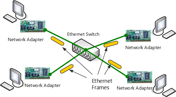
Switching Hub and network adapter for Ethernet.
MAC Address
Computers participating in Ethernet must communicate with IDs to prevent them from duplicating each other. Each network adapter has been assigned a unique 48-bit ID. This 48-bit ID is referred as "MAC address". As a rule, the MAC address of the physical network adapter has been assigned, computers would not be duplicated anywhere in the world (in the case of software network adapter such as SoftEther VPN Virtual Network Adapter, a suitable algorithm whereby possibility of MAC address actually being duplicated is extremely low is generated to prevent duplication).
Communication Packets (Ethernet Frames) that Flow through Ethernet
Communication packets that flow through Ethernet are commonly referred to as "Ethernet frames" or "MAC frame Ethernet packets" (in this manual they are uniformly referred to as "Ethernet frames"). Ethernet frames contain several headers and the data to be actually transmitted (payload). The following four items are the most important of these.
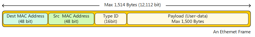
A Ethernet frame (MAC frame).
The destination MAC address (48 bits) is a field which contains the MAC address that recovers indicating to which computer the Ethernet frames of the computer sending the frames will be sent. Relaying devices such as a switching Hub within Ethernet reads the destination MAC address and relay the Ethernet frames.
The source MAC address (48 bits) is the field containing the MAC address of the network adapter of the computer sending the Ethernet frames.
Protocol type (16 bits) indicates in a 16-bit value what protocol the data contained in the Ethernet frame (payload) uses in layer 3. For example the value is 0x0800 for IP and 0x0806 for ARP. In some cases the field may contain a value that indicates the length of the payload instead of the protocol type, but it is currently not used often.
The payload (maximum 1500 bytes) is the data to be actually transmitted using Ethernet.
Unicast and Broadcast
There are two ways that Ethernet frames can be sent, "unicast" and "broadcast". "Unicast" is when an Ethernet frame is sent by specifying the MAC address of a certain network adapter. And as for "broadcast" is the frame that sent to all network adapters participating in Ethernet other than your own.
When sending frames by unicast, the MAC address of the destination network adapter is specified for destination MAC address. And when sending frames by broadcast, the special MAC address FF:FF:FF:FF:FF:FF is specified as the destination MAC address. The frames of which the MAC address destination FF:FF:FF:FF:FF:FF are called "broadcast packets" or "broadcast frames". And as a rule this can be received by all computers (network adapters) participating in the Ethernet network.
Switching Hub Mechanism
The switching Hub used by Ethernet (layer 2 switch) constructs a network by Ethernet and it is an important peripheral device for communication. Switching Hubs have multiple ports (usually 8 ports, but can have from tens to hundreds). By connecting a compute to the Ethernet by network cable, etc., a physical network is connected between the switching Hub and computer's network adapter, thus enabling Ethernet communications by layer 2.
The ports of a switching Hub can also be connected to the ports of another switching Hub. Even though the connected switching Hubs were originally separate by Ethernet networks, by connecting them by network cable, they work like a single Ethernet network. This is called "cascade connection".
The computers connected to the switching Hubs on the left and right in the following figure (Segment junction by cascade connection of switching hubs.) can communicate freely with each other.
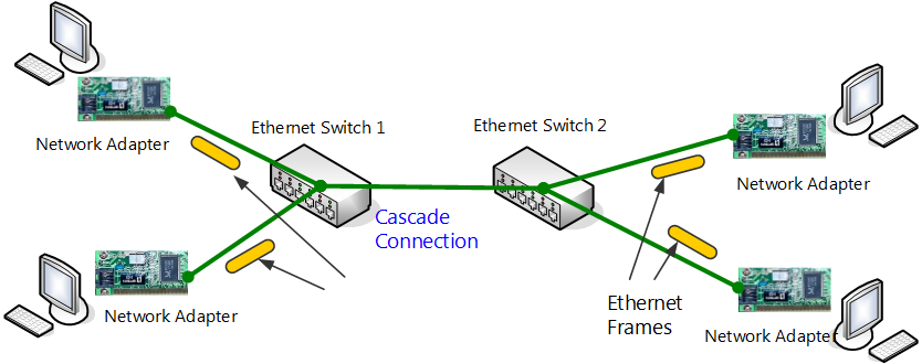
Segment junction by cascade connection of switching hubs.
Frame Exchange and MAC Address Learning by Switching Hub
Switching Hubs constantly recognize in advance which computers with what sort of MAC address are connected to the respective ports and maintain the information in an internal database. This is called a "MAC address table".
When a switching Hub receives an Ethernet frame, it reads the destination MAC address of the Ethernet frame, and when the destination MAC address is registered in the MAC address table, it is sent to the concerned port. If the destination MAC address is not registered in the MAC address table or the Ethernet frame is a broadcast frame, it will be sent to all ports.
The processing whereby a switching Hub learns new MAC addresses and registers them in the internal MAC address table is carried out automatically by reading the source MAC address, each time a new Ethernet frame will be received.
This realizes function whereby unicast packets are only sent to required ports, and are not sent to unnecessary ports. This is called the "Frame exchange and MAC address learning by switching Hub function".
Ethernet Segment (Broadcast Domain)
In examples thus far, a single network through which computers participating in an Ethernet network can communicate freely with each other is called an "Ethernet segment," a "segment" or "broadcast domain". An Ethernet configured of a switching Hub is usually one segment. A segment can also be formed by connecting two originally separate segments by network cable, etc., as was previously mentioned.
Cascade Connection
As it has been mentioned earlier, the method of connecting two segments configured of two switching Hubs and using as a single segment is called "cascade connection". Cascade connection can consist of an unlimited number of cascades provided the physical limit established for Ethernet is not exceeded. The fact is that cascade connection can be accomplished easily and it is one of the greatest features of using Ethernet. By cascade connecting another switching Hub to one for which the number of ports has become insufficient, you can increase the number of available ports and increase the number of computers that can be connected to the network.
Bridge Connection
Bridge connection enables frames to be exchanged freely by cascade connection of two physically separated Ethernet segments or similar configuration.
Cascade connection and bridge connection are technically similar connection methods, but whereas cascade connection indicates connecting switching Hubs to construct a single large segment from the beginning, bridge connection means connecting networks to be used as two segments that are physically separate and are administered separately.
1.4.2 Virtual Hub
With SoftEther VPN by creating a virtual switching Hub and network adapter, VPN communication that creates virtual Ethernet is realized. This section contains a brief description of Virtual Hub. A more concrete description of Virtual Hub is provided in 1.6 VPN Communication Details.
Virtual Hub Functions
Virtual Hub is one of the most important functions of SoftEther VPN. Virtual Hub implements the same level of functions as the existing common layer 2 switching Hub as software. Virtual Hub has a MAC address learning function and frame exchange/delivery functions based on learning. Whereas conventional switching Hubs used to handle this processing as hardware, with Virtual Hub of SoftEther VPN, the processing is handled as software.
For details concerning realization of VPN communications by Virtual Hub, see 1.6 VPN Communication Details and 3.4 Virtual Hub Functions.
SoftEther VPN Server can create multiple Virtual Hubs. You can create as many Virtual Hubs as memory space, CPU speed and specifications will permit. Each respective Virtual Hub conducts MAC address learning for virtual Ethernet frames flowing through the VPN. As a result virtual layer 2 Ethernet segments are realized by sending Ethernet frames to computers participating in other VPNs.
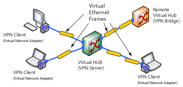
Connection between Virtual Hubs or between Virtual Network Adapters.
Creation and Administration of Multiple Virtual Hubs
When multiple Virtual Hubs are created within a single VPN server, those Virtual Hubs cannot communicate with each other. Consequently if multiple Virtual Hubs are created, it means multiple Ethernet segments are formed within the VPN Server.
Unlike the physical switching Hub in conventional Ethernet, the Virtual Hub of SoftEther VPN is connected by TCP/IP-based tunneling protocol (SoftEther VPN protocol) via an existing IP network (such as the Internet) rather than direct connection by network cable. In other words, there is a function whereby a virtual port equal to port connected to a physical switching Hub by network cable stands by for connection to the Virtual Hub, enabling VPN connection by SoftEther VPN protocol, just like as if it is connected by network cable to virtual port from another computer.
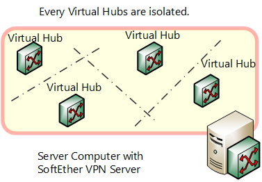
Segment separation by Virtual Hub within VPN Server.
Role of Administration Unit
As was previously mentioned, you can connect to Virtual Hub from a remote location by SoftEther VPN protocol, but when the connection is permitted by anybody, a third party whom is not permitted can connect to the Virtual Hub. To prevent this the administrator defines users who can connect to the Virtual Hub, and can set so that only users successfully authenticated are accepted (either password authentication or certificate authentication may be used). Concerning communication within the Virtual Hub as well, permitting all communication contents by default but applying packet filtering and security policy, some types of communication can be blocked.
These setting contents are completely independent for each Virtual Hub, and administration is divided into units so each individual administrator can administrate it separately. Administrators of VPN Servers at large can manage all Virtual Hubs, but administrators granted authority concerning some Virtual Hubs from the VPN Server administrator can manage only those Virtual Hubs and those are unable to manage other Virtual Hubs.
Method of Connecting Virtual Hubs to each other
Virtual Hubs can be cascade connected to Virtual Hubs operating on the same VPN Server or VPN Server operating on another computer, and the cascade connected Virtual Hubs that were originally separate segments are joined to work as a single segment.
For Virtual Hubs operating on the same VPN Server, via virtual layer 3 switch by IP routing, network among Virtual Hubs can be connected by layer 3.
1.4.3 Virtual Network Adapter
With SoftEther VPN, a physical switching Hub can be made virtual to realize Virtual Hub. Similarly, a physical network adapter can be made virtual by software to realize a Virtual Network Adapter. Virtual Network Adapter can connect to a Virtual Hub operating within SoftEther VPN Server at a remote location through a network by TCP/IP-based SoftEther VPN protocol.
For details concerning SoftEther VPN Client and Virtual Network Adapter, see 4. SoftEther VPN Client Manual.
SoftEther VPN Virtual Network Adapter recognized as a network adapter by the operating system.
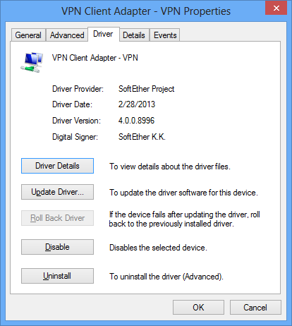
Virtual Network Adapter software is currently offered as a SoftEther VPN Client for Windows and Linux. Computers installed with SoftEther VPN Client can connect the VPN Server as a VPN client. Multiple Virtual Network Adapters can be created on a client computer as a SoftEther VPN Client setting. Because the created Virtual Network Adapter is recognized as a network adapter just as physical network adapter by almost any communications application is running on the operating system, as a rule almost all network protocols that support Ethernet communications and TCP/IP protocol can communicate on VPN via Virtual Hub.
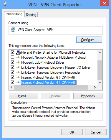
Property window of Virtual Network Adapter.
1.4.4 Cascade connection and virtual layer 3 switch
With SoftEther VPN Server, you can create multiple Virtual Hubs and operate them at the same time. In the initial state however Virtual Hubs have only independent layer 2 segments, and although computers connected to the same Virtual Hub can communicate freely, computers connected to separate Virtual Hubs cannot communicate with each other.
Cascade Connection
Using the cascade connection function, you can connect to a Virtual Hub on which the same VPN Server or other computer's VPN Server is operating. By combining cascade connection and bridge connection functions, you can easily construct base-to-base connection VPN. For details on cascade connection, see 3.4 Virtual Hub Functions. For examples of VPN construction combining cascade and bridge connection functions, see 10.5 Build a LAN-to-LAN VPN (Using L2 Bridge).
Virtual Layer 3 Switch
The virtual layer 3 switch function emulates a communications device for IP routing by IP protocol called "layer 3 switch" or "IP router".
Layer 3 switches and IP routers can be joined as a layer 3 IP network with physically separated layer 2 segments with split broadcast domain. In this case layer 2 segments separated by IP routing that communicate via layer 3 switch or router and IP packets can arrive at another network across networks sequentially via 3 switch or router. Massive IP networks such as the Internet are realized by combination of layer 3 switch and router.
Using the virtual layer 3 switch function of SoftEther VPN Server enables IP routing among multiple Virtual Hubs. When conducting IP routing among multiple Virtual Hubs with the previous version of SoftEther 1.0, etc., you had to conduct IP routing with a physical layer 3 switch or special router by bridge connecting each respective Virtual Hub segment to a physical Ethernet segment. However SoftEther VPN Server's support of virtual layer 3 switch function enables network administrators to easily realize communication among Virtual Hubs by IP routing among multiple Virtual Hubs.
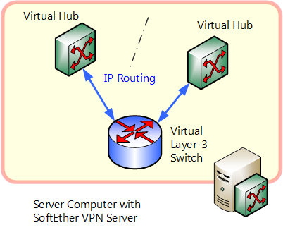
IP routing among Virtual Hubs by virtual layer 3 switch.
When connecting multiple networks bases by VPN by SoftEther VPN, a combination of local bridge function and cascade connection function is usually sufficient, but if connecting networks to each other by VPN, you might have to use a combination of IP routing by virtual layer 3 switch function. For VPN construction examples using virtual layer 3 switch function, see 10.6 Build a LAN-to-LAN VPN (Using L3 IP Routing).
1.4.5 Bridge Connection of Virtual Network and Physical Network
SoftEther VPN Server and SoftEther VPN Bridge are equipped with a local bridge function. Using the local bridge function enables you to bridge connect Virtual Hub and physical network adapter. In other words, you can join two segments such as Virtual Hub and existing physical network as a single segment. For details see 3.6 Local Bridges.
By connecting Virtual Hub and physical existing LAN by multiple bases and by furthermore cascade connecting Virtual Hubs existing physical LAN of multiple bases can be easily made a single segment via Internet to realize base-to-base VPN.
Example of base-to-base connection by SoftEther VPN.
1.4.6 Computer-to-computer VPN
Networks that realize SoftEther VPN can roughly be divided into the following three forms:
- Computer-to-computer VPN
- Remote access VPN
- Base-to-base connection VPN
A sophisticated VPN can be constructed by separating or combining these forms. For actual network construction examples, see 10. Examples of Building VPN Networks.
Computer-to-computer VPN is the simplest form of VPN built using SoftEther VPN. The range of communication via VPN that can be constructed extremely easily, is not very wide .
With computer-to-computer VPN, for Virtual Hub of SoftEther VPN Server established at one location, multiple computers connecting network adapter of SoftEther VPN Client to Virtual Hub by VPN is enable any Ethernet frame to be sent or received among computers participating in VPN. So that the communication can be carried out freely and safely without depending on physical network form. All VPN communication is encrypted to prevent eavesdropping and tampering.
With computer-to-computer VPN, however, computers installed with SoftEther VPN Client can communicate freely, but computers other than these cannot participate in VPN.
For specific connection method, see 10.3 Build a PC-to-PC VPN.
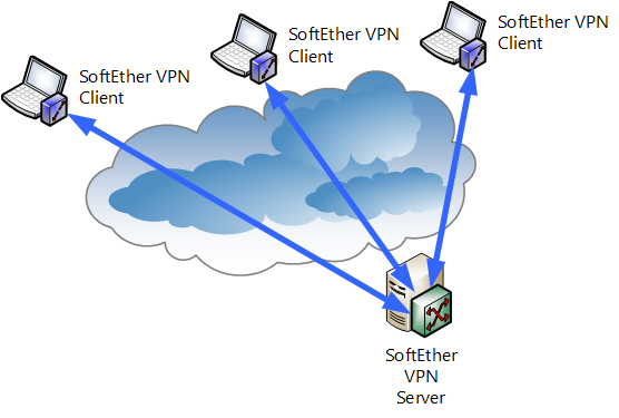
Computer-to-computer VPN.
1.4.7 Remote Access VPN
Remote access VPN is a type of VPN that can be built by using SoftEther VPN. You can freely access the computers out in the field or at home that cannot be accessed from Internet such as common company LAN, and can communicate with the application of your choice.
From before remote access to company LAN has been frequently accomplished by using PPP protocol by dial-up network such as telephone line or ISDN. Communication speed for these methods is however low, and because it was pay-as-you-go, it was difficult to send or receive a large quantities of data that had taken an extended amount of time.
With remote access VPN by SoftEther VPN, by installing SoftEther VPN Client, as a rule, as long as you had an environment where the Internet could be connected to, you could easily connect by VPN to a SoftEther VPN Server set up in company LAN from anywhere in the world, thereby enabling company LAN access. All VPN communication is also encrypted to prevent eavesdropping and tampering.
In order to realize remote access VPN, a SoftEther VPN Server is established in the company LAN and the Virtual Hub and existing physical Ethernet segment created in VPN Server that are connected by bridge connection. Connecting by computer installed with VPN Client from remote to concern the Virtual Hub enables the remote access to company LAN.
With conventional VPN protocol, even protocols other than TCP/IP that has been hard to use in many cases will c be used via virtual Ethernet. VPN sessions can furthermore be easily established via proxy servers, firewall or NAT that use to be hard for conventional VPN protocol to get through.
For specific connection method, see 10.4 Build a Generic Remote Access VPN.
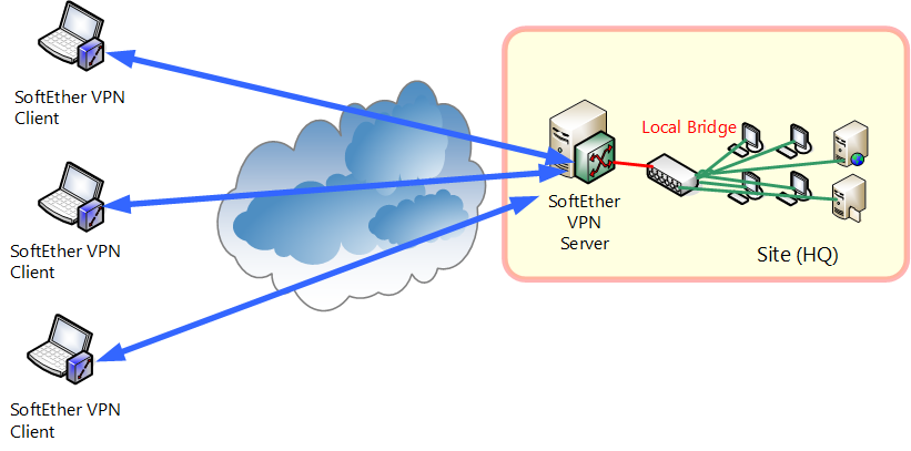
Remote access VPN.
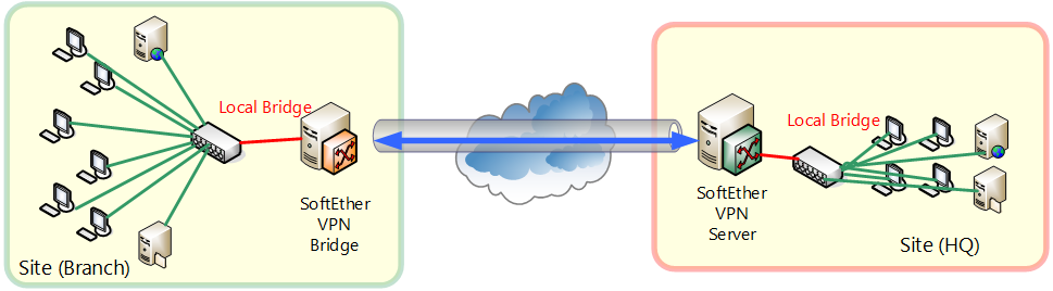
1.4.8 Base-to-Base VPN of Ordinary Scale
Remote access VPN is the form of VPN that enables multiple computers installed with VPN Client to access one base via Internet or other bases from a remote location.
Base-to-base VPN, on the other hand it is a VPN connection method whereby multiple bases in physically separated locations that can connect with each other. It is probably the best way for companies or departments where two or more bases already exist or are considering increasing the number of bases.
With base-to-base VPN, the set up computers installed with VPN Server or VPN Bridge at multiple bases and connecting existing physical Ethernet segments of each base and Virtual Hub within the VPN Server or VPN Bridge by local bridge connection. Virtual Hub of another VPN Bridge, etc., is connected by cascade connection to VPN Server of one of several bases. By doing so, physical layer 2 segments of multiple separated bases recognize each other as a single segment. After physical networks among multiple bases are connected to each other, so they can be used as a single segment by SoftEther VPN, they are used just as if they are physically connected by cascade connection using an extremely long network cable. All VPN communication is also encrypted to prevent eavesdropping and tampering.
Base-to-base connection VPN function to bridge bases can realize economic and secure service through the Internet that is the same as that of conventional broadband Ethernet service as communication carriers.
For specific connection method, see 10.5 Build a LAN-to-LAN VPN (Using L2 Bridge).

Base-to-base VPN of ordinary scale.
1.4.9 Base-to-Base VPN of Large Scale
The method of connecting physical Ethernet segments of multiple bases such as by the previously described base-to-base VPN connection of ordinary scale works well if there are a total of several hundred clients at each base connected by VPN, but if the number of computers exceeds this when totaled and you want to connect respective computers to each other, several limitations such as the following may occur.
- If the number of computers exceeds several hundred, the volume of communication by protocol using broadcast frames such as ARP and NetBIOS increases and increases the load of VPN connection among bases.
- Because networks that were originally separate become a single large network with the system of connecting layer 2 segments alike, as a rule, it is preferable that computers in the segments belong to the same IP network, but if the total number of computers is too large, it will costs a lot to alter the configuration.
In the case where such limitations may pose problems, by combining the virtual layer 3 switch function, layer 2 local bridge function and cascade connection function of SoftEther VPN Server, you can use IP routing by layer 3 instead of direct cascade connection of base networks by layer 2. Using this method is especially effective if realizing large scale base-to-base connection VPN. This however requires knowledge of IP routing for designing and building and improves level of difficulty. For specific connection method, see 10.6 Build a LAN-to-LAN VPN (Using L3 IP Routing).
By this method, same or better base-to-base VPN communication supported older VPN protocols such as PPTP and L2TP/IPSec can be easily realized by SoftEther VPN software.
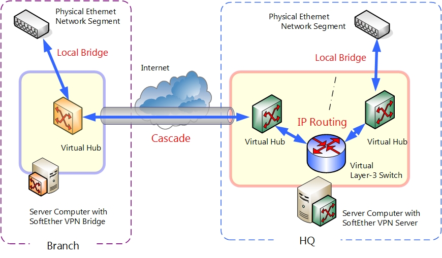
Base-to-base VPN of large scale.
See Also
- 1.6 VPN Communication Details
- 3.4 Virtual Hub Functions
- 3.4 Virtual Hub Functions
- 3.6 Local Bridges
- 10. Examples of Building VPN Networks
- 10.3 Build a PC-to-PC VPN
- 10.4 Build a PC-to-LAN Remote Access VPN
- 10.5 Build a LAN-to-LAN VPN (Using L2 Bridge)
- 10.6 Build a LAN-to-LAN VPN (Using L3 IP Routing)